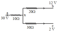
Figure shows a part of an electric circuit. The potentials at points $a , b$ and $c$ are $30\,V , 12\,V$ and $2\,V$ respectively. The current through the $20 \Omega$ resistor will be $........\,A$
JEE MAIN 2023, Diffcult


Download our appand get started for free
Experience the future of education. Simply download our apps or reach out to us for more information. Let's shape the future of learning together!No signup needed.*
Similar Questions
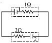
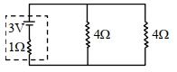
- 1In the figure shown, battery $1$ has $\mathrm{emf}$ $= 6\, V$ and internal resistance $= 1 \,\Omega$. Battery $2$ has $\mathrm{emf}$ $= 2\,V$ and internal resistance $= 3\, \Omega$ . The wires have negligible resistance. What is the potential difference across the terminals of battery $2$ ? ................ $V$View Solution
- 2If two bulbs of wattage $25$ and $30$, each rated at $220\, volts$, are connected in series with a $440$ $volt$ supply, which bulb will fuseView Solution
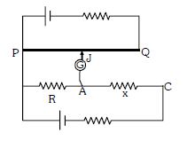
- 3Circuit for the measurement of resistance by potentiometer is shown. The galvanometer is first connected at point $A$ and zero deflection is observed at length $P J = 10\ cm$ . In second case it is connected at point $C$ and zero deflection is observed at a length $30\ cm$ from $P$ . Then the unknown resistance $X$ isView Solution
- 4The drift velocity of free electrons in a conductor is ‘$v$’ when a current ‘$i$’ is flowing in it. If both the radius and current are doubled, then drift velocity will beView Solution
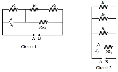
- 5In Circuit-$1$ and Circuit- $2$ shown in the figures, $R_1=1 \Omega, R_2=2 \Omega$ and $R_3=3 \Omega$. $P_1$ and $P_2$ are the power dissipations in Circuit-$1$ and Circuit-$2$ when the switches $S_1$ and $S_2$ are in open conditions, respectively. $Q_1$ and $Q_2$ are the power dissipations in Circuit-$1$ and Circuit-$2$ when the switches $S_1$ and $S_2$ are in closed conditions, respectively.View Solution
Which of the following statement($s$) is(are) correct?
$(A)$ When a voltage source of $6 V$ is connected across $A$ and $B$ in both circuits, $P_1$
$(B)$ When a constant current source of $2 Amp$ is connected across $A$ and $B$ in both circuits, $P_1>P_2$.
$(C)$ When a voltage source of $6 V$ is connected across $A$ and $B$ in Circuit-$1$, $Q_1>P_1$.
$(D)$ When a constant current source of $2 Amp$ is connected across $A$ and $B$ in both circuits, $Q_2$
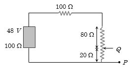
- 6In the circuit, the potential difference across $PQ$ will be nearest to .............. $V$View Solution
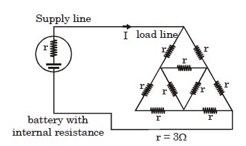
- 7By which of the following single load resistance the load bridge should be replaced so that the power to the load remains unchanged ................ $\Omega$View Solution
- 8View SolutionIn the given circuit, the terminal potential difference of the cell is:
- 9If two electric bulbs have $40\,W$ and $60\,W$ rating at $220\,V$, then the ratio of their resistances will beView Solution
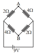
- 10A network of four resistances is connected to $9\,V$ battery, as shown in figure. The magnitude of voltage difference between the points $A$ and $B$ is .......... $V.$View Solution