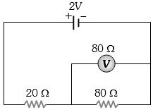
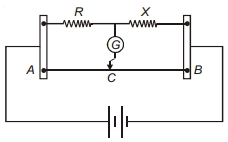
In the adjoining circuit, the $e.m.f.$ of the cell is $2\, volt$ and the internal resistance is negligible. The resistance of the voltmeter is $80 \,ohm$. The reading of the voltmeter will be ............. $volt$
Medium
Download our app for free and get started
(c) Total resistance of the circuit $ = \frac{{80}}{2} + 20 = 60\,\Omega $
$ \Rightarrow $ Main current $i = \frac{2}{{60}} = \frac{1}{{30}}A$
Combination of voltmeter and $80$ $\Omega$ resistance is connected in series with $20$ $\Omega$, so current through $20$ $\Omega$ and this combination will be same $ = \frac{1}{{30}}A$.
Since the resistance of voltmeter is also $80$ $\Omega$, so this current is equally distributed in $80$ $\Omega$ resistance and voltmeter (i.e.$\frac{1}{{60}}A$ through each)
$P.D.$ across $80$ $\Omega$ resistance $ = \frac{1}{{60}} \times 80 = 1.33\,V$

Download our appand get started for free
Experience the future of education. Simply download our apps or reach out to us for more information. Let's shape the future of learning together!No signup needed.*
Similar Questions
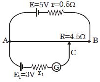
- 1In the given potentiometer circuit length of the wire $AB$ is $3\,m$ and resistance is $R = 4.5 \,\Omega.$ The length $AC$ for no deflection in galvanometer is ................ $\mathrm{m}$View Solution
- 2What equal length of an iron wire and a copper-nickel alloy wire, each of $2 \; {mm}$ diameter connected parallel to give an equivalent resistance of $3 \Omega ?$View Solution
(Given resistivities of iron and copper-nickel alloy wire are $12 \;\mu \Omega {cm}$ and $51\; \mu \Omega {cm}$ respectively) (in ${m}$)
- 3To get maximum current through a resistance of $2.5\,\Omega $, one can use $m$ rows of cells, each row having $n$ cells. The internal resistance of each cell is $0.5\,\Omega $. What are the values of $n$ and $m$ if the total number of cells is $45$ ?View Solution
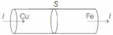
- 4Two rods of copper and iron with the same cross-sectional area are joined at $S$ and a steady current $I$ flows through the rods as shown in the figure. Choose the most appropriate representation of charges accumulated near the junction $S$.View Solution
- 5In the meter bridge shown, the resistance $X$ has a negative temperature coefficient of resistance. Neglecting the variation in other resistors, when current is passed for some time, in the cirucit, balance point should shift towards.View Solution
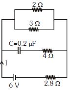
- 6In the given figure the steady state current $I$ is ................. $\mathrm{A}$View Solution
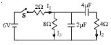
- 7In the circuit shown in the figure, the switch $S$ is initially open and the capacitor is initially uncharged. $ I_1, I_2$ and $I_3$ represent the current in the resistance $2\,\Omega , 4\,\Omega $ and $8\,\Omega$ respectively.View Solution
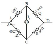
- 8In a Wheatstone bridge, $P = 90\,\Omega $, $Q = 110\,\Omega $ , $R = 40\,\Omega $ and $S = 60\,\Omega $ and a cell of $4\,V\,emf$. Then the potential difference between the diagonal along which a galvanometer is connected is ............. $V$View Solution
- 9In the circuit shown in Figure the ammeter reads a current ............. $A$View Solution
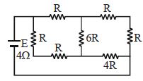
- 10A battery of internal resistance $4\, ohm$ is connected to the network of resistance as hown. In the order that the maximum power can be delivered to the network, the value of $R$ in ohm should be :-View Solution