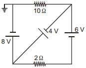
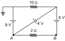
In the circuit shown in figure, all cells are ideal. The current through $2 \,\Omega$ resistor is ............ $A$
Medium


Download our appand get started for free
Experience the future of education. Simply download our apps or reach out to us for more information. Let's shape the future of learning together!No signup needed.*
Similar Questions
- 1Assume a hypothetical wire in which free electron density changes with temperature in proportionality $n\ \alpha \ T$ assuming $\tau $(Relaxation time of collision) and dimensions of wire remain unchanged with increasing temperature. Which one of the resistance $v/s$ temperature graph is trueView Solution
- 2View SolutionIf the length of potentiometer wire is increased, then the length of the previously obtained balance point will
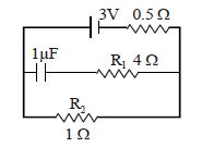
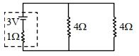
- 3A $1\,\mu F$ capacitor is connected in the circuit shown below. The emf of the cell is $3\ volts$ and internal resistance is $0.5\ ohms$ . The resistors $R_1$ and $R_2$ have values $4\ ohms$ and $1\ ohm$ respectively. The charge on the capacitor in steady state must be.......$\mu C$View Solution
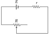
- 4A battery of $e.m.f.$ $E$ and internal resistance $r$ is connected to a variable resistor $R$ as shown here. Which one of the following is trueView Solution
- 5A cell of negligible resistance and $e.m.f.$ $2$ $volts$ is connected to series combination of $2$, $3$ and $5\, ohm$. The potential difference in volts between the terminals of $3\, ohm$ resistance will beView Solution
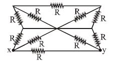
- 6What will be equivalent resistance of circuit between $x$ and $y$View Solution
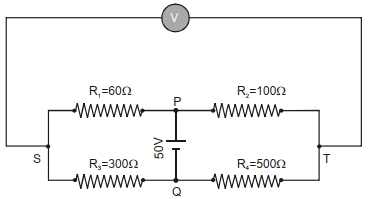
- 7In the balanced condition, the values of the resistances of the four arms of a Wheatstone bridge are shown in the figure below. The resistance $R_3$ has temperature coefficient $0.0004{ }^{\circ} C ^{-1}$. If the temperature of $R_3$ is increased by $100{ }^{\circ} C$, the voltage developed between $S$ and $T$ will be. . . . . . . volt.View Solution
- 8View SolutionIn the given circuit, the terminal potential difference of the cell is:
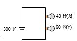
- 9Two bulbs $X$ and $Y$ having same voltage rating and of power $40\, watt$ and $60\, watt$ respectively are connected in series across a potential difference of $300\, volt$, thenView Solution
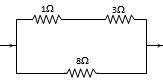
- 10Power dissipated across the $8 \,\,\Omega$ resistor in the circuit shown here is $2\,\, watt.$ The power dissipated in watt units across the $3 \,\,\Omega$ resistor isView Solution