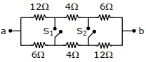
In the given figure switches $S_{1}$ and $S_{2}$ are in open condition. The resistance across $a b$ when the switches $S_{1}$ and $S_{2}$ are closed is $...\,\Omega$
JEE MAIN 2021, Diffcult
Download our app for free and get started
$\frac{12 \times 6}{12+6}+2+\frac{6 \times 12}{6+12}$
$\frac{72}{18}+2+\frac{72}{18}=4+2+4=10\, \Omega$

Download our appand get started for free
Experience the future of education. Simply download our apps or reach out to us for more information. Let's shape the future of learning together!No signup needed.*
Similar Questions
- 1The length of a potentiometer wire is $l$. $A$ cell of $\mathrm{emf}$ $E$ is balanced at a length $l/3$ from the positive end of the wire. If the length of the wire is increased by $l/2$. At what distance will the same cell give a balance point.View Solution
- 2As the switch $S$ is closed in the circuit shown in figure, current passed through it is .............View Solution
- 3Which of the following wiring diagrams could be used to experimentally determine $R$ using ohm's law? Assume an ideal voltmeter and an ideal ammeter.View Solution
- 4A meter bridge is set up as shown, to determine an unknown resistance ' $X$ ' using a standard $10\,ohm$ resistor. The galvanometer shows null point when tapping-key is at $52\,cm$ mark. The endcorrections are $1\,cm$ and $2\,cm$ respectively for the ends $A$ and $B$. The determined value of ' $X$ ' is $..........\Omega$View Solution
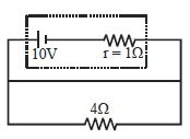
- 5Potential difference across the terminals of the battery shown in figure is .................... $V$ ($r =$ internal resistance of battery)View Solution
- 6Consider four conducting materials copper, tungsten, mercury and aluminium with resistivity $\rho_{ C }, \rho_{ T }, \rho_{ M }$ and $\rho_{ A }$ espectively Then:View Solution
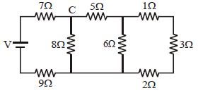
- 7In the ladder network shown, current through the resistor $3\, \Omega$ is $0.25\,A$. The input voltage $'V'$ is equal to:- ........... $V$View Solution
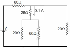
- 8A current of $0.1 \,A$ flows through a $25 \,\Omega$ resistor represented by the circuit diagram. The current in $80 \,\Omega$ resistor is ........... $A$View Solution
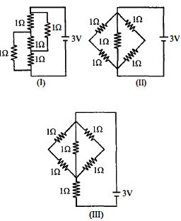
- 9The figure shows three circuits $I, II$ and $III$ which are connected to a $3\,V$ battery. If the powers dissipated by the configurations $I, II$ and $III$ are $P_1 , P_2$ and $P_3$ respectively, thenView Solution
- 10Two wires that are made up of two different materials whose specific resistance are in the ratio $2 : 3$, length $3 : 4$ and area $4 : 5$. The ratio of their resistances isView Solution