Which of the following wiring diagrams could be used to experimentally determine $R$ using ohm's law? Assume an ideal voltmeter and an ideal ammeter.
Medium
Download our app for free and get started
Ohm's law states that current through the conductor between two points is directly proportional to the potential difference across the two points.
Which can be represented by circuit diagram as below.

Download our appand get started for free
Experience the future of education. Simply download our apps or reach out to us for more information. Let's shape the future of learning together!No signup needed.*
Similar Questions
- 1For a cylinder of radius $R$ current density $J =J_0 \frac{r}{R} $, where $J_0$ is a constant and $r$ is distance from axis. Calculate total currentView Solution
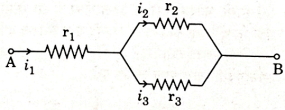
- 2Three resistors having resistances $\mathrm{r}_{1}, \mathrm{r}_{2}$ and $\mathrm{r}_{3}$ are connected as shown in the given circuit. The ratio $\frac{i_{3}}{i_{1}}$ of currents in terms of resistances used in the circuit is :View Solution
- 3An electric bulb is rated $60\,W$, $220\,V$. The resistance of its filament is ............. $\Omega$View Solution
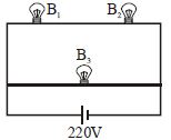
- 4A $100\, W \, bulb\, B_1$ and two $60\, W \,bulbs \,B_2$ and $B_3$, are connected to a $220\, V$ source, as shown in Figure. Now $P_1, P_2$ and $P_3$ are the output powers of the bulbs $B_1, B_2$ and $B_3$ respectively. ThenView Solution
- 5The given figure shows $a$ network of resistances and $a$ battery. Which of the two batteries is getting charged?View Solution
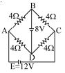
- 6In the given network current through branch $BG$ is almost equal to ............ $A$View Solution
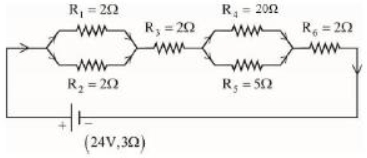
- 7As shown in the figure, a network of resistors is connected to a battery of $2\,V$ with an internal resistance of $3\,\Omega$. The currents through the resistors $R_4$ and $R_5$ are $I_4$ and $I_5$ respectively. The values of $I_4$ and $I_5$ are :View Solution
- 8$A$ uniform copper wire carries a current $i$ amperes and has $p$ carriers per meter$^3$. The length of the wire is $\lambda$ meters and its cross-section area is $s$ meter $^2$. If the charge on a carrier is $q$ coulombs, the drift velocity in $ms^{-1}$ is given byView Solution
- 9A wire of resistance $160\,\Omega$ is melted and drawn in wire of one-fourth of its length. The new resistance of the wire will be $......\Omega$View Solution
- 10View SolutionTo draw maximum current from a combination of cells, how should the cells be grouped