Ratio of thermal energy released in two resistor $R$ and $3 R$ connected in parallel in an electric circuit is :
JEE MAIN 2023, Easy
Download our app for free and get started
$H =\frac{ V ^2}{ R } \times t$
$\frac{ H _1}{ H _2}=\frac{\frac{ V ^2 t }{ R }}{\frac{ V ^2 t }{3 R }}=3: 1$

Download our appand get started for free
Experience the future of education. Simply download our apps or reach out to us for more information. Let's shape the future of learning together!No signup needed.*
Similar Questions
- 1Three $60\, W$ light bulbs are mistakenly wired in series and connected to a $120\,V$ power supply. Assume the light bulbs are rated for single connection to $120\,V$. With the mistaken connection, the power dissipated by each bulb is: .................. $W$View Solution
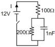
- 2Find the charge in steady state of the capacitor. (in $nC)$View Solution
- 3A uniform wire of resistance $R$ is uniformly compressed along its length, until its radius becomes $n$ times the original radius. Now resistance of the wire becomesView Solution
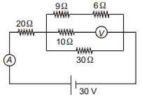
- 4In the circuit shown in figure, if ammeter and voltmeter are ideal, then the power consumed in $9 \,\Omega$ resistor will be .......... $W$View Solution
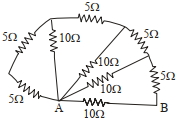
- 5The equivalent resistance between points $A$ and $B$ in the given network is ............ $\Omega$View Solution
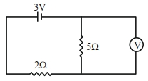
- 6As shown in the figure, the voltmeter reads $2\,V$ across $5\,\Omega$ resistor. The resistance of the voltmeter is $.......\,\Omega$.View Solution
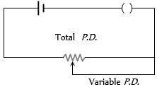
- 7View SolutionThe arrangement as shown in figure is called as
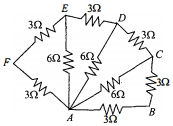
- 8Six resistors of $3 \;\Omega$ each are connected along the sides of a hexagon and three resistors of $6\; \Omega$ each are connected along $A C, A D$ and $A E$ as shown in the figure. The equivalent resistance between $A$ and $B$ is equal toView Solution
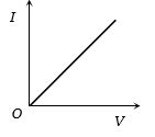
- 9$I-V$ characteristic of a copper wire of length $L$ and area of cross-section $A$ is shown in figure. The slope of the curve becomesView Solution
- 10View SolutionIn the circuit shown in the figure below, which of the following statement is incorrect ?