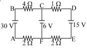
The figure shows a network of four resistances and three batteries The current through the branch $CF$ is ............... $A$
Diffcult
Download our app for free and get started

Download our appand get started for free
Experience the future of education. Simply download our apps or reach out to us for more information. Let's shape the future of learning together!No signup needed.*
Similar Questions
- 1If the balance point is obtained at the $35^{th} cm$ in a meter bridge the resistances in the left and right gaps are in the ratio ofView Solution
- 2A wire when connected to $220\,V$ mains supply has power dissipation ${P_1}$. Now the wire is cut into two equal pieces which are connected in parallel to the same supply. Power dissipation in this case is ${P_2}$. Then ${P_2}:{P_1}$ isView Solution
- 3View SolutionThe capacitor shown in fig. is in steady state. The energy stored in the capacitor is
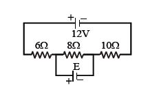
- 4In the circuit shown, the current through $8\,ohm$ issame before and after connecting $E$. The value of $E$ is .................... $\mathrm{V}$View Solution
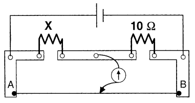
- 5A meter bridge is set-up as shown, to determine an unknown resistance ' $X$ ' using a standard $10$ ohm resistor. The galvanometer shows null point when tapping-key is at $52 \ cm$ mark. The end-corrections are $1 \ cm$ and $2 \ cm$ respectively for the ends $A$ and $B$. The determined value of ' $X$ ' isView Solution
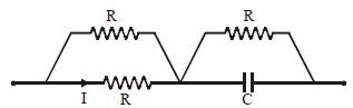
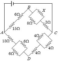
- 6In the figure given the value of $X$ resistance will be, when the $p.d.$ between $B$ and $D$ is zero ................... $ohm$View Solution
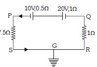
- 7View SolutionIn the circuit shown in the figure below, which of the following statement is incorrect ?
- 8A $5.0\, amp$ current is setup in an external circuit by a $6.0\, volt$ storage battery for $6.0$ minutes. The chemical energy of the battery is reduced byView Solution
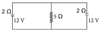
- 9In the arrangement shown in figure, the current through $5\,\Omega$ resistor is ............. $A$View Solution
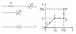
- 10In the circuit shown below (on the left) the resistance and the emf source are both variable. The graph of seven readings of the voltmeter and the ammeter ( $V$ and $I$, respectively) for different settings of resistance and the emf, taken at equal intervals of time $\Delta t$, are shown below (on the right) by the dots connected by the curve $E F G H$. Consider the internal resistance of the battery to be negligible and the voltmeter an ammeter to be ideal devices. (Take, $R_0 \equiv \frac{V_0}{I_0}$ ).View Solution
Then, the plot of the resistance as a function of time corresponding to the curve $E F G H$ is given by