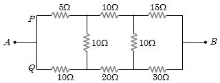
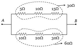
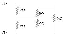
In the arrangement of resistances shown below, the effective resistance between points $A$ and $B$ is ............... $\Omega$
Medium


Download our appand get started for free
Experience the future of education. Simply download our apps or reach out to us for more information. Let's shape the future of learning together!No signup needed.*
Similar Questions
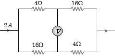
- 1In the circuit shown below, The reading of the voltmeter $V$ is ...........View Solution
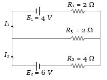
- 2In the circuit shown below $E_1 = 4.0 \,V, R_1= 2 \Omega, E_2 = 6.0 \,V, R_2 = 4 \,\Omega$ and $R_3 = 2 \,\Omega$. The current $I_1$ is ..................... $A$View Solution
- 3The specific resistance of a wire is $\rho $, its volume is $3\,{m^3}$ and its resistance is $3\, ohms$, then its length will beView Solution
- 4A battery of $24$ cells, each of emf $1.5\, V$ and internal resistance $2\, \Omega$ is to be connected in order to send the maximum current through a $12 \,\Omega$ resistor. The correct arrangement of cells will beView Solution
- 5View SolutionResistance of one carbon filament and one tungsten lamp are measured individually when the lamp are lit and compared with their respective resistances when cold. Which one of the following statements will be true
- 6Find the equivalent resistance across $AB$ .............. $\Omega$View Solution
- 7Temperature coefficient at $0\,^oC$ is $0.00125\,^oC^{-1}$. At a temperature of $25\,^oC$ its resistance is $1\,\Omega $. Find the temperature at which resistance is $1.2\,\Omega $View Solution
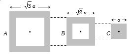
- 8Following figure shows cross-sections through three long conductors of the same length and material, with square cross-section of edge lengths as shown. Conductor $B$ will fit snugly within conductor $A$, and conductor $C$ will fit snugly within conductor $B$. Relationship between their end to end resistance isView Solution
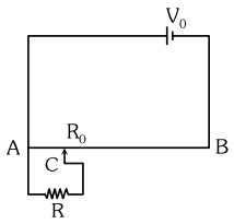
- 9The sliding contact $C$ is at one fourth of the length of the potentiometer wire $( AB )$ from $A$ as shown in the circuit diagram. If the resistance of the wire $AB$ is $R _0$, then the potential drop $( V )$ across the resistor $R$ isView Solution
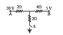
- 10As the switch $S$ is closed in the circuit shown in figure, current passing through it is ................ $\mathrm{A}$View Solution