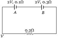
The internal resistances of two cells shown are $0.1\,\Omega $ and $0.3\,\Omega $. If $R = 0.2\,\Omega $, the potential difference across the cell
Medium
Download our app for free and get started
Applying Kirchhoff law
$(2 + 2) = (0.1 + 0.3 + 0.2)i$ $ \Rightarrow $ $i = \frac{{20}}{3}\,A$
Hence potential difference across $A$
$ = 2 - 0.1 \times \frac{{20}}{3} = \frac{4}{3}\,V$ (less than $2\,V$)
Potential difference across $B = 2 - 0.3 \times \frac{{20}}{3} = 0$

Download our appand get started for free
Experience the future of education. Simply download our apps or reach out to us for more information. Let's shape the future of learning together!No signup needed.*
Similar Questions
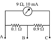
- 1A milliammeter of range $10\, mA$ and resistance $9\, \Omega$ is joined in a circuit as shown. The meter gives full-scale deflection for current $I$ when $A$ and $B$ are used as its terminals, i.e., current enters at $A$ and leaves at $B$ ($C$ is left isolated). The value of $I$ isView Solution
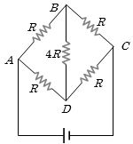
- 2Five resistors of given values are connected together as shown in the figure. The current in the arm $BD$ will beView Solution
- 3View SolutionIn potentiometer a balance point is obtained, when
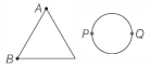
- 4A uniform metallic wire of length $L$ is mounted in two configurations. In configuration $1$ (triangle), it is an equilateral triangle and a voltage $V$ is applied to corners $A$ and $B$. In configuration $2$ (circle), it is bent in the form of a circle and the potential $V$ is applied at diametrically opposite points $P$ and $Q$. The ratio of the power dissipated in configuration $1$ to configuration $2$ isView Solution
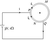
- 5A wire of resistance $10$ $\Omega$ is bent to form a circle. $P$ and $Q$ are points on the circumference of the circle dividing it into a quadrant and are connected to a Battery of $3\, V$ and internal resistance $1$ $\Omega$ as shown in the figure. The currents in the two parts of the circle areView Solution
- 6In a potentiometer experiment, the galvanometer shows no deflection when a cell is connected across $60\, cm$ of the potentiometer wire. If the cell is shunted by a resistance of $6\,\Omega $, the balance is obtained across $50\, cm$ of the wire. The internal resistance of the cell is .............. $\Omega $View Solution
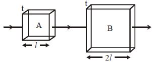
- 7Two square metal plates $A$ and $B$ are of the same thickness and material. The side of $B$ is twice that of $A$. These are connected as shown in series. If the resistances of $A$ and $B$ are denoted by $R_A$ and $R_B,$ then $(R_A/R_B)$ isView Solution
- 8The current in the given circuit is ................ $A$View Solution
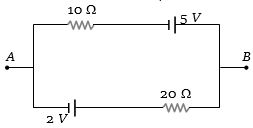
- 9The value of current through the $20\,\Omega $ resistor is ............ $amp$View Solution
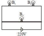
- 10A $100\, W \, bulb\, B_1$ and two $60\, W \,bulbs \,B_2$ and $B_3$, are connected to a $220\, V$ source, as shown in Figure. Now $P_1, P_2$ and $P_3$ are the output powers of the bulbs $B_1, B_2$ and $B_3$ respectively. ThenView Solution